Heavy Hex Bolts ISO
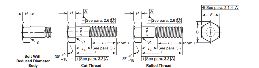
ASME B18.2.3.6 Dimensions of Heavy Hex Bolt ISO
All dimensions are in mm unless mentioned otherwise
| Nominal Size or Basic Product Diameter | Full-Size Body Diameter, E | Width Across Flats, F | Width Across Corners, G | Head Height, H Basic | Radius of Fillet, R | Nominal Thread Length for Bolt Lengths, LT | |||||||||
| inch | mm | Max | Min | Basic inch | Max | Min | Max | Min | Basic inch | Max | Min | Max | Min | 6 in. and Shoter | Over 6 in. |
| 3⁄8 | 0.3750 | 0.388 | 0.360 | 11⁄16 | 0.688 | 0.669 | 0.794 | 0.763 | 1⁄4 | 0.268 | 0.226 | 0.03 | 0.01 | 1.000 | 1.250 |
| 1⁄2 | 0.5000 | 0.515 | 0.482 | 7⁄8 | 0.875 | 0.850 | 1.010 | 0.969 | 11⁄32 | 0.364 | 0.302 | 0.03 | 0.01 | 1.250 | 1.500 |
| 5⁄8 | 0.6250 | 0.642 | 0.605 | 1 1⁄16 | 1.062 | 1.031 | 1.227 | 1.175 | 27⁄64 | 0.444 | 0.378 | 0.06 | 0.02 | 1.500 | 1.750 |
| 3⁄4 | 0.7500 | 0.768 | 0.729 | 1 1⁄4 | 1.250 | 1.212 | 1.443 | 1.383 | 1⁄2 | 0.524 | 0.455 | 0.06 | 0.02 | 1.750 | 2.000 |
| 7⁄8 | 0.8750 | 0.895 | 0.852 | 1 7⁄16 | 1.438 | 1.394 | 1.660 | 1.589 | 37⁄64 | 0.604 | 0.531 | 0.06 | 0.02 | 2.000 | 2.250 |
| 1 | 1.0000 | 1.022 | 0.976 | 1 5⁄8 | 1.625 | 1.575 | 1.876 | 1.796 | 43⁄64 | 0.700 | 0.591 | 0.09 | 0.03 | 2.250 | 2.500 |
| 1 1⁄8 | 1.1250 | 1.149 | 1.098 | 1 13⁄16 | 1.812 | 1.756 | 2.093 | 2.002 | 3⁄4 | 0.780 | 0.658 | 0.09 | 0.03 | 2.500 | 2.750 |
| 1 1⁄4 | 1.2500 | 1.277 | 1.223 | 2 | 2.000 | 1.938 | 2.309 | 2.209 | 27⁄32 | 0.876 | 0.749 | 0.09 | 0.03 | 2.750 | 3.000 |
| 1 3⁄8 | 1.3750 | 1.404 | 1.345 | 2 3⁄16 | 2.188 | 2.119 | 2.526 | 2.416 | 29⁄32 | 0.940 | 0.810 | 0.09 | 0.03 | 3.000 | 3.250 |
| 1 1⁄2 | 1.5000 | 1.531 | 1.470 | 2 3⁄8 | 2.375 | 2.300 | 2.742 | 2.622 | 1 | 1.036 | 0.902 | 0.09 | 0.03 | 3.250 | 3.500 |
| 1 5⁄8 | 1.6250 | 1.658 | 1.591 | 2 9⁄16 | 2.562 | 2.481 | 2.959 | 2.829 | 1 3⁄32 | 1.116 | 0.978 | 0.09 | 0.03 | 3.500 | 3.750 |
| 1 3⁄4 | 1.7500 | 1.785 | 1.716 | 2 3⁄4 | 2.750 | 2.662 | 3.175 | 3.035 | 1 5⁄32 | 1.196 | 1.054 | 0.12 | 0.04 | 3.750 | 4.000 |
| 1 7⁄8 | 1.8750 | 1.912 | 1.839 | 2 15⁄16 | 2.938 | 2.844 | 3.392 | 3.242 | 1 1⁄4 | 1.276 | 1.130 | 0.12 | 0.04 | 4.000 | 4.250 |
| 2 | 2.0000 | 2.039 | 1.964 | 3 1⁄8 | 3.125 | 3.025 | 3.608 | 3.449 | 1 11⁄32 | 1.388 | 1.175 | 0.12 | 0.04 | 4.250 | 4.500 |
| 2 1⁄4 | 2.2500 | 2.305 | 2.214 | 3 1⁄2 | 3.500 | 3.388 | 4.041 | 3.862 | 1 1⁄2 | 1.548 | 1.327 | 0.19 | 0.06 | 4.750 | 5.000 |
| 2 1⁄2 | 2.5000 | 2.559 | 2.461 | 3 7⁄8 | 3.875 | 3.750 | 4.474 | 4.275 | 1 21⁄32 | 1.708 | 1.479 | 0.19 | 0.06 | 5.250 | 5.500 |
| 2 3⁄4 | 2.7500 | 2.827 | 2.711 | 4 1⁄4 | 4.250 | 4.112 | 4.907 | 4.688 | 1 13⁄16 | 1.869 | 1.632 | 0.19 | 0.06 | 5.750 | 6.000 |
| 3 | 3.0000 | 3.081 | 2.961 | 4 5⁄8 | 4.625 | 4.475 | 5.340 | 5.102 | 2 | 2.060 | 1.815 | 0.19 | 0.06 | 6.250 | 6.500 |
Heavy Hex Bolt Metric
ASME B18.2.3.6M Dimensions of Heavy Hex Bolt Metric
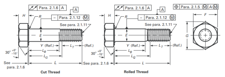
| Pitch | Body Diameter, E | AF, F | AC, G | Head Height, H | Minimum Fillet Radius, R | Thread Length, LT, Ref. | Maximum Transition Thread Length, Y, Ref. | Maximum Runout of Bearing Surface FIM | ||||
| Max. | Min. | Max. | Min. | Max. | Min. | Max. | Min. | |||||
| M12 X 1.75 | 12.7 | 11.3 | 21 | 20.16 | 24.25 | 22.78 | 7.95 | 7.05 | 0.6 | 25 | 5.2 | 0.4 |
| M16 X 2 | 16.7 | 15.3 | 27 | 26.16 | 31.18 | 29.56 | 10.75 | 9.25 | 0.6 | 31 | 6 | 0.5 |
| M20 X 2.5 | 20.84 | 19.16 | 34 | 33 | 39.26 | 37.29 | 13.4 | 11.6 | 0.8 | 36 | 7.5 | 0.6 |
| M22 X 2.5 | 22.84 | 21.16 | 36 | 35 | 41.57 | 39.55 | 14.9 | 13.1 | 0.8 | 38 | 7.5 | 0.6 |
| M24 X 3 | 24.84 | 23.16 | 41 | 40 | 47.34 | 45.2 | 15.9 | 14.1 | 1 | 41 | 9 | 0.7 |
| M27 X 3 | 27.84 | 26.16 | 46 | 45 | 53.12 | 50.85 | 17.9 | 16.1 | 1.2 | 44 | 9 | 0.8 |
| M30 X 3.5 | 30.84 | 29.16 | 50 | 49 | 57.74 | 55.37 | 19.75 | 17.65 | 1.2 | 49 | 10.5 | 0.9 |
| M36 X 4 | 37 | 35 | 60 | 58.8 | 69.28 | 66.44 | 23.55 | 21.45 | 1.5 | 56 | 12 | 1 |